View planes
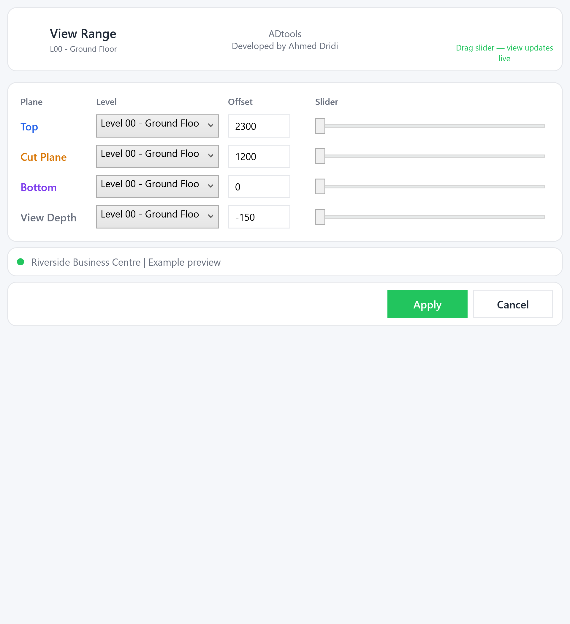
Set Top, Cut Plane, Bottom and View Depth, selecting the associated level.

VR — View Range — brings the four view-range planes into a compact interface. Values use project units and can be adjusted without navigating successive native dialogs.
Set Top, Cut Plane, Bottom and View Depth, selecting the associated level.
Enter and adjust offsets in the project’s length units.
Preview changes live before confirming the view range.
Specific handling of ceiling plans and certain structural views when Revit imposes relationships between planes.
The interface distinguishes Top, Cut Plane, Bottom and View Depth. Each row combines a level, offset and slider to clarify the active view range.
Move sliders or enter a value and press Enter. The view updates during adjustment so you can observe the effect on visible elements.
Check heights and view depth, then use Apply to retain the settings or Cancel to leave the dialog.
To understand why an element is not visible in a plan, adjust the cut plane and view depth while watching the display change.
In the modelL00 - Ground Floor view.
In the extensionTop: 2,300 mm; Cut Plane: 1,200 mm; Bottom: 0 mm; View Depth: −150 mm.
Check the resultObserve visibility in the view, then apply the chosen range.
Illustrative example: the windows are populated with a fictional English-language Revit project, “Riverside Business Centre”.